Description:
VK-IPCE-10 instrument can be used to measure Incident Photon-to-electron Conversion Efficiency (IPCE) and spectral response (SR) characteristics of photovoltaic cells or photo-sensors. Conventional IPCE measurement setups basically consist of a light source (Halogen or Xenon), monochromator, chopper, lock-in amplifier, and calibrated Si photodiode. To use such a setup you should have prior experience and proper training to operate the wavelength-scanner, lock-in-amp, chopper, light source, and should manually do light intensity measurement using calibrated reference Si photodiode. The main drawback of conventional IPCE setups is that incident-monochromatic-light-intensity measurement and user sample measurement performed in two separate steps, and we have to assume the light intensity is constant during those two measurements. But in reality, any light source can have slight intensity variations with time. Reference cell and user sample positioning also play a major role in the accuracy of final results. You must have experience and proper knowledge to operate several different instruments including a lock-in amp. The simplified operation procedure of VK-IPCE-10 overcomes all of the above drawbacks and gives you a unique experience. You can control all the functions of this instrument using a single user interface on your personal computer wirelessly. IPCE measurement on your sample can be performed in 3 simple steps as follows: 1. Mount the device on the sample stage. 2. Open desired measurement setup file. 3. Click the [START SCAN] button. You don't need any special training or experience to operate this setup. We have automated the whole process and all of the settings and calibration data that need to be set before start measurement is saved in a file. You just need to open the desired measurement setting file, it will automatically set and turn on the required component for the measurement. You can very easily create your new measurement setup and save it as a new file for future use. VK-IPCE-10 is an integrated single unit without attached measuring instruments such as a lock-in-amplifier. It utilizes a powerful microcontroller-based digital signal processing technique to synchronize the detection of extremely low current signals. A beam-splitter-based double beam technique is implemented to perform real-time light intensity measurement (to perform user sample and reference cell measurements simultaneously), hence optimized the accuracy of the IPCE measurements.
Features:
- This compact instrument with fully automatic operation allows user to perform IPCE measurement by one click.
- User-friendly simple operation interface allows to start measurement quickly without reading bulky manuals and setting up various parameters.
- State-of-the-art Bluetooth communication allows user to control all the functions remotely.
- No attached equipments such as lock-in amplifier, source meter, and lamp power supply, only the main power switch needs to turn on.
- Utilize 100 % Digital Signal Processing (DSP) technique with Fast Fourier Transform (FFT) to measure synchronous current produced with chopped light beam.
- The double beam technique with a Si reference cell measures sample current & light intensity simultaneously.
- The motorized sample mounting stage aligns sample precisely.
|
IPCE & Spectral Response Measurement System |
| Type of Measurement
|
Incident Photon-to-electron Conversion Efficiency (IPCE), Spectral response (A/W)
|
| Wavelength Range
|
340 - 1000 nm (calibrated photo diode limits). 0 - 1400 nm mechanical limit.
|
| Light Source
|
Halogen Photo Optic Lamp (OSRAM XENOPHOT®) 3400 K. Life time of Halogen lamp is greatly enhanced due to variable power operation technique where lamp is operated at less than half of rated power.
|
| Irradiation modes |
Natural (Halogen lamp spectrum)
Constant energy
Constant photon
(Constant energy or photon Irradiation mode is achieved by controlling the halogen lamp current. Automatic calibration process is performed the calibration of lamp current to keep constant energy or photon output).
|
| Irradiation monochromatic light power on sample |
1 to 100 μW (400 - 1000 nm range) |
Measuring technique |
Optically chopped (1 – 21 Hz) light beam is split into two parts (double beam technique) then incident on Device-Under-Test (DUT), and calibrated Si reference (REF) cell. Simultaneously digitized DUT and REF signals (short circuit currents) were Fast Fourier Transform (FFT) to obtain power spectrum (filter out only the chopped frequency component).
|
Grating
|
1200G / 500nm blaze. |
Filters
|
Up to 5 different high-order light cut filters can be installed. L-37 and R-64 installed. |
Recommended sample size
|
10 mm x 10 mm |
White light (bias) source |
Three watts white LED (output power can be set through the software). |
Sample mounting stage
|
This system equipped with motorized sample mounting stage. User can remotely switch the sample and standard Si photo diode in order to do baseline calibration or verify accuracy of measurements.
|
User Interface and data collection |
Computer software is provided free of charge to control all of the functions and data logging. Measurement data can be saved as a text file and directly plotted on ®Microsoft Excel graph. User interface is designed such that normal user can be performed measurements by setting just the scan wavelength range. Also advanced user can control hardware settings such as grating and filter changing position FFT bin size and also able to get raw I vs. t and FFT data.
|
Communication |
Bluetooth |
Power Requirement |
100 – 240 VAC (50-60 Hz)
Input voltage selection switch available to set the correct input voltage range.
|
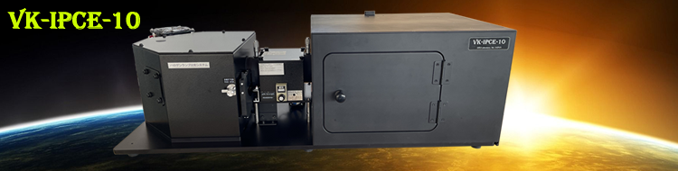
Dimensions
Weight |
91 cm x 47 cm x 29 cm
20 kg |
PC |
Windows based PC is needed to install control software, despite not included to the standard setup and can be added as a option.
|
|
Download Controll Software (Free):
VK-IPCE-10 Version 1 control software
VK-IPCE-10 Version 2 control software
Download pdf version of brochure
|
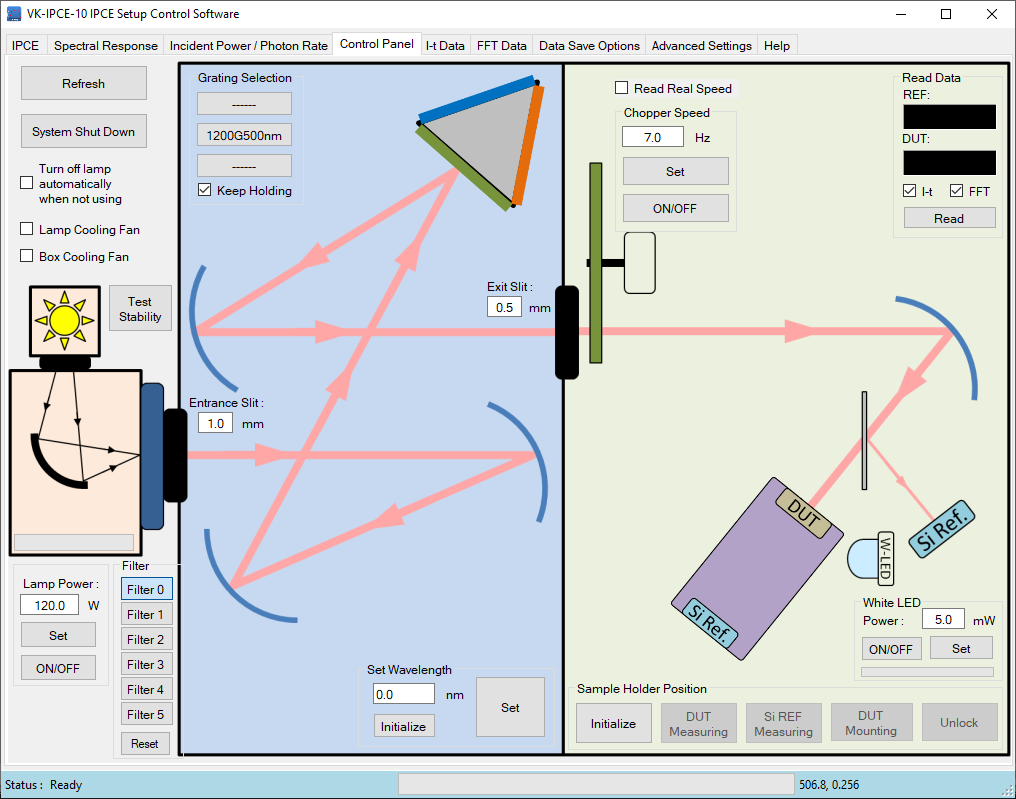
“Control Panel” tab allows user to control all of functions such as sample stage position, lamp current, chopper speed, and filters. Also user can measure both output of the sample and reference at desired wavelength
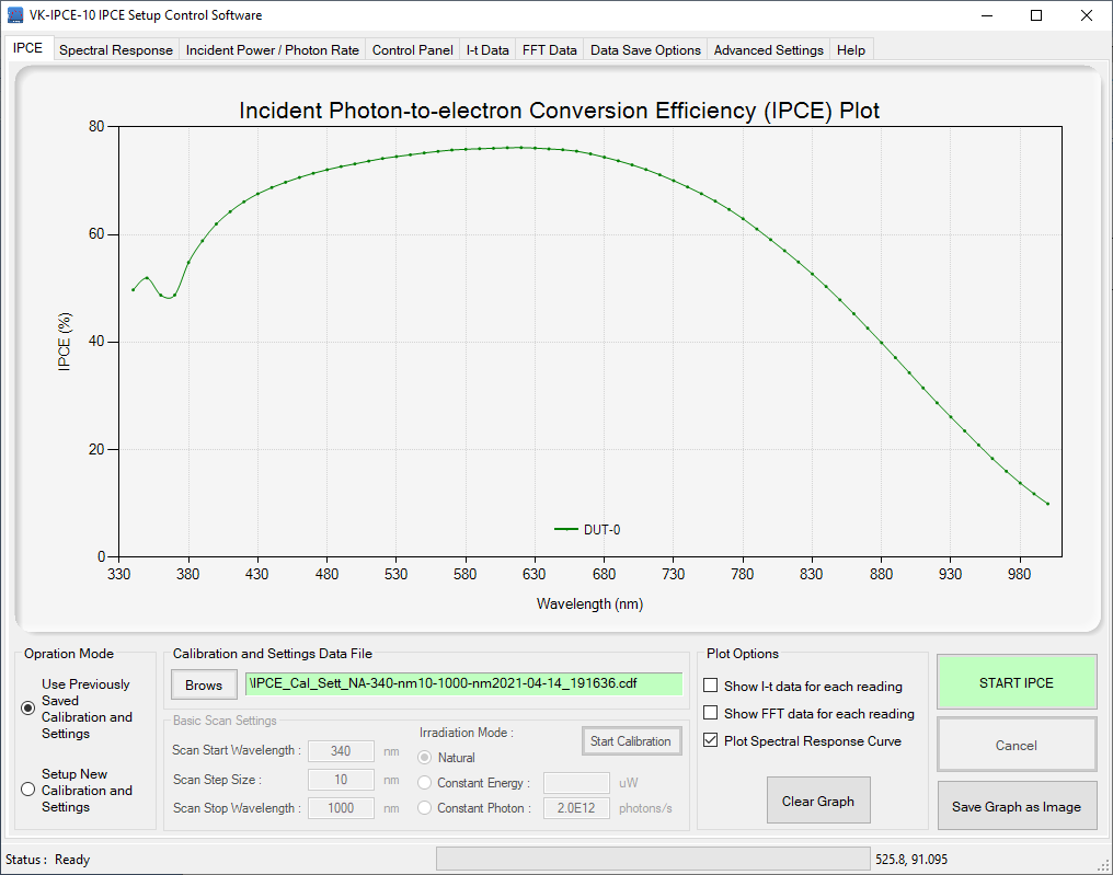
“IPCE” tab of the control software allows user to set scan range, Irradiation mode, and plot options. Also user can open previously saved baseline calibration curve or start new calibration curve. Si photo diode was used as a sample for reference.
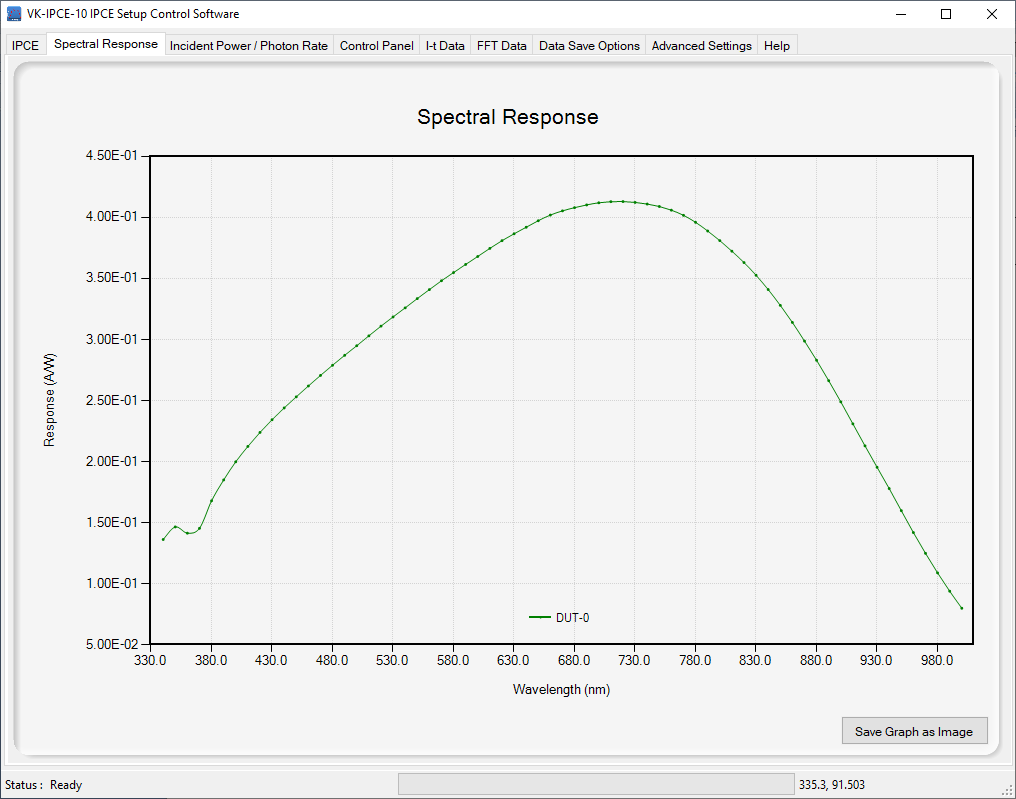
“Spectral Response” tab shows the spectral sensitivity (A/W) curve of measured sample. Si photo diode was used as a sample in this example.
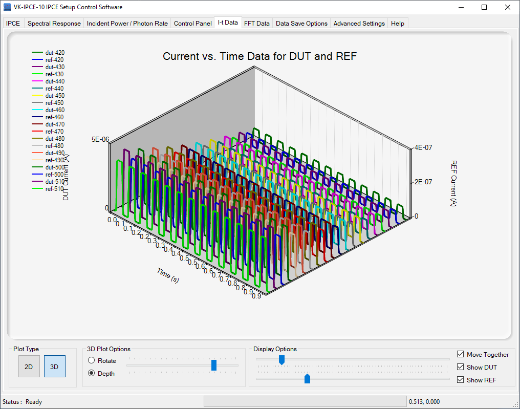
“I-t Data” tab shows the time domain data taken for each measurement point. User can view data as 2D or 3D plot for select number of measurement points.
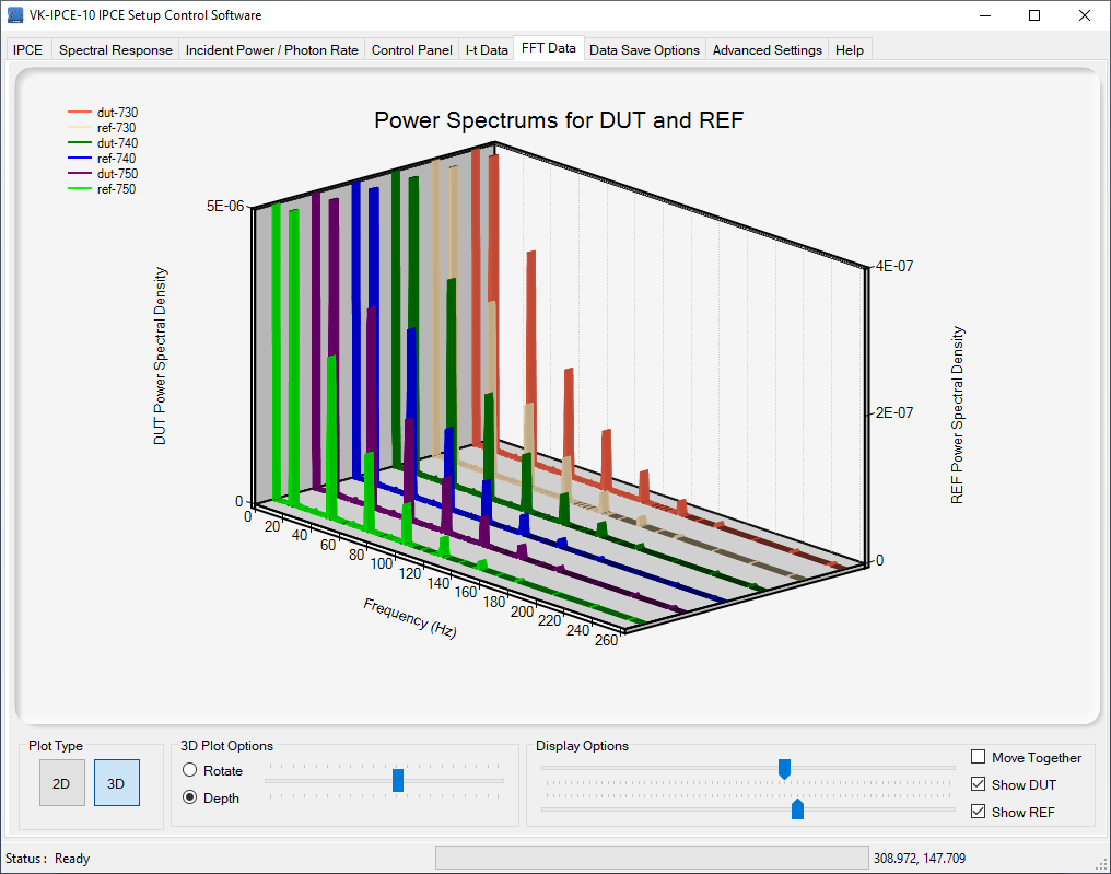
“FFT Data” tab shows the Fourier transformed data for each measurement point. User can view data as 2D or 3D plot for select number of measurement points.
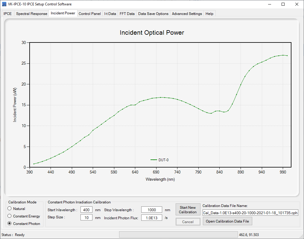
Incident optical power on the sample during an IPCE measurement with natural irradiation mode. In this mode halogen lamp operating current keeps at a user set fixed value.
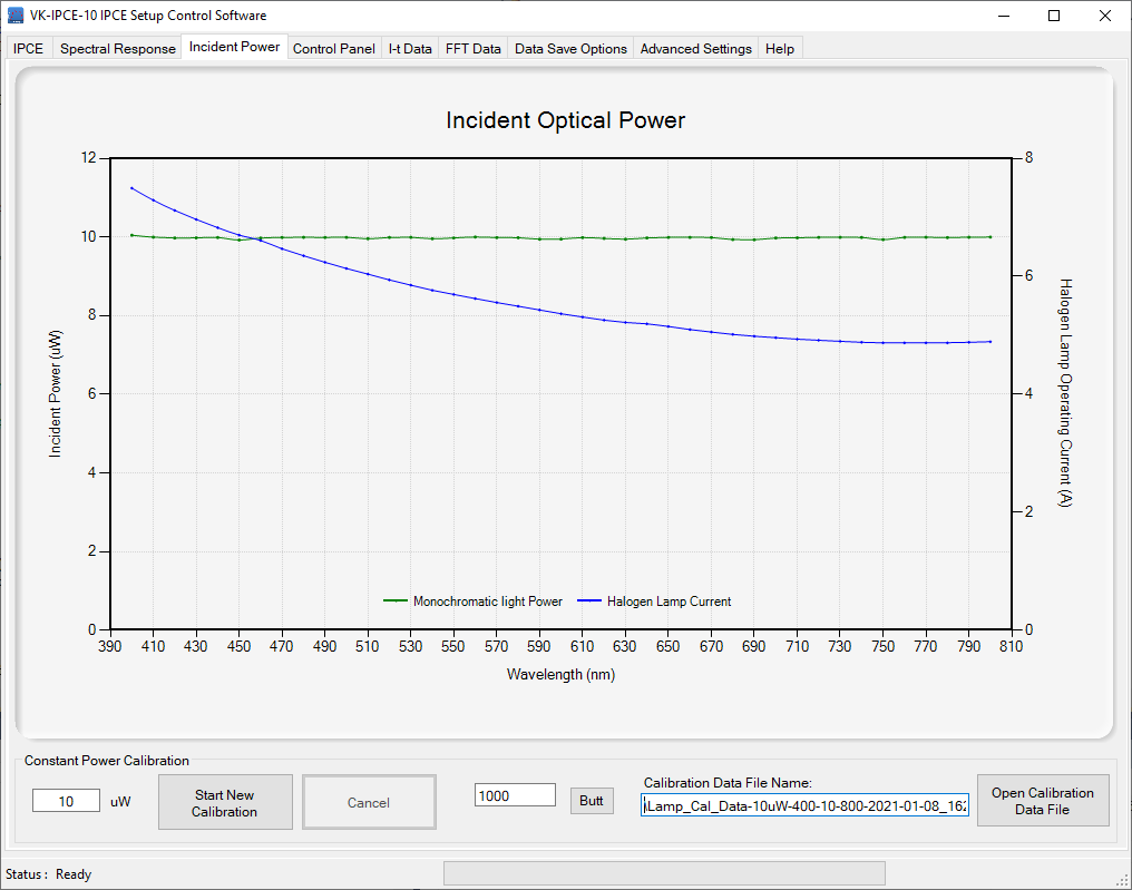
Lamp calibration curve taken for constant energy irradiation mode. Green curves shows 10 μW constant incident optical power on the sample and blue curve shows the halogen lamp current variation for keeps constant power on the sample.
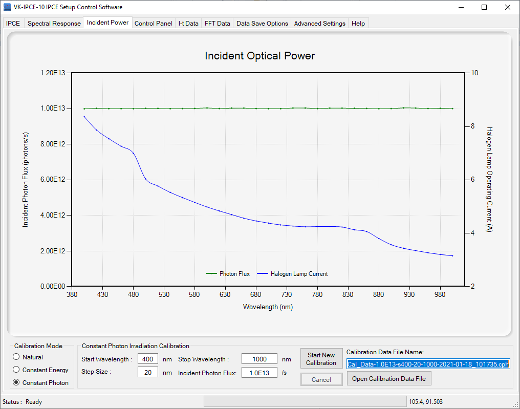
Lamp calibration curve taken for constant photon irradiation mode. Green curves shows 1.0E13 /s constant photon flux on the sample and blue curve shows the halogen lamp current variation to keeps the constant photon flux on the sample.
|